Monday, November 30, 2015
Arduino ESP8226-13 (ESP-13) By a Noob 4 a Noob
I have never needed to use WiFi in any of my projects thus far and I always assumed it would be pretty hard to integrate. I came across the ESP8226 very lately (2015) and after reading many online references I thought I’d give it a shot.
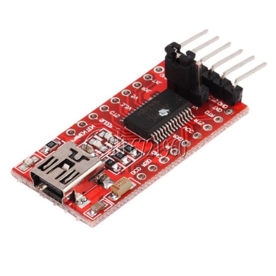
I purchased the latest and greatest ESP-13 for a few bucks($3) together with a FTDI ($2) off e-bay I had no idea why I needed the FTDI except that it was mentioned in quite a few online ESP tutorials.
For this topic, some background is required to set the scene.
FTDI What???
In order to communicate/program the ESP-13 module we need to be able to send serial communication from our PC to the ESP device.
Future Technology Devices International (FTDI) is a company that makes USB->Serial ICs. One famous one that I have purchased is the FT232RL. (notice the 232 reference i.e from back in the RS232 days). The module that I purchased off e-bay allows our PCs to expose a serial port over USB and send serial communication to an external device on COM ports. (Side note, if you had a very old PC with a serial port you would not need this FTDI board).
ESP What???
Now to the magical ESP chip manufactured by Espressif Systems. The ESP8266 is a module that incorporates a Microcontroller IC and a Flash storage IC. The microcontroller is pretty sweet in that is operates in the 40 ->160MHz range and with the external flash you can have access to 2MB of storage.
So the ESP is a microcontroller with some storage… but how the heck do I use it?
Reminder that I’m a noob with regards to these ESP chips so this is my understanding.
The ESP-13 (or any other ESP module) can be run as is because it is has preset/preloaded WiFi software stack. what does this mean? It can detect//connect/transmit over WiFi using a few commands that it understands (AT commands). AT commands refer to the Hayes command set commonly used to communicate with modems. AT stands for ATtention. So by supplying the chip with power and setting a few configuration pins accordingly (as defined in the datasheet) you can effectively boot the device into a “slave mode” config. In this mode the RX/TX lines allow us to send and receive AT command and information between our PC and the ESP module.
Alternatively the ESP module can be used as a microcontroller that runs your code. Remember the microcontroller is used to facilitate the WiFi software stack but like any microcontroller has GPIO, PWM, ADC, UART, I2C, I2S, IRDA functionality. This means that you can write your own code and program it directly to this chip. (<--- I have not used this method yet)
ESP-13
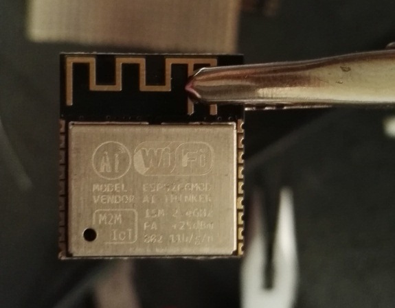
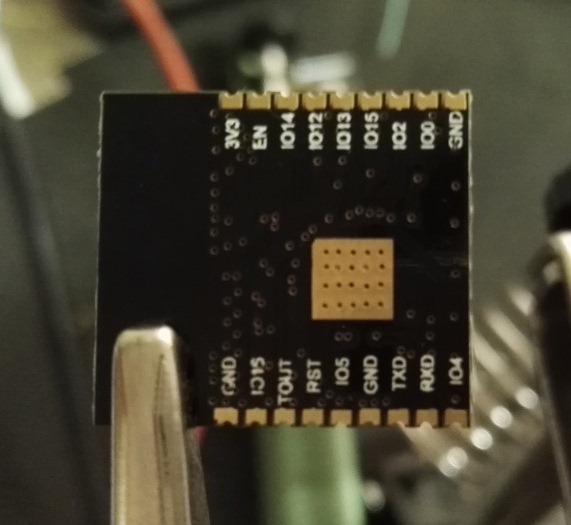
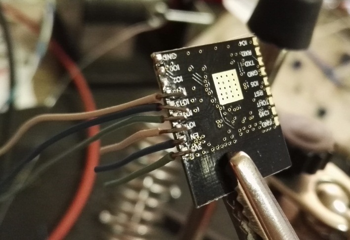
The ESP-13 module that I bought has printed on it ESP_WROOM_02 this is the datasheet that you will find on the Espressif site. To use this chip, I needed to solder (with great precision) a break out board to use it on breadboard.
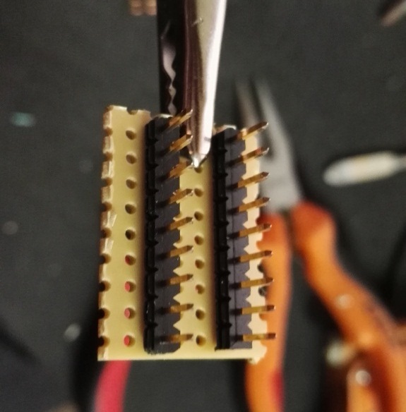
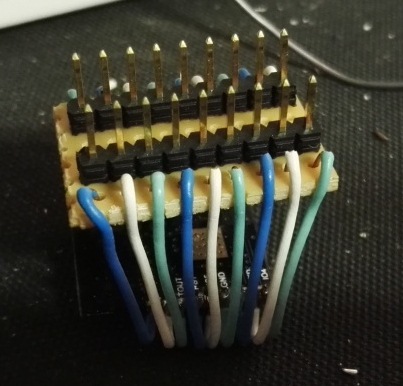
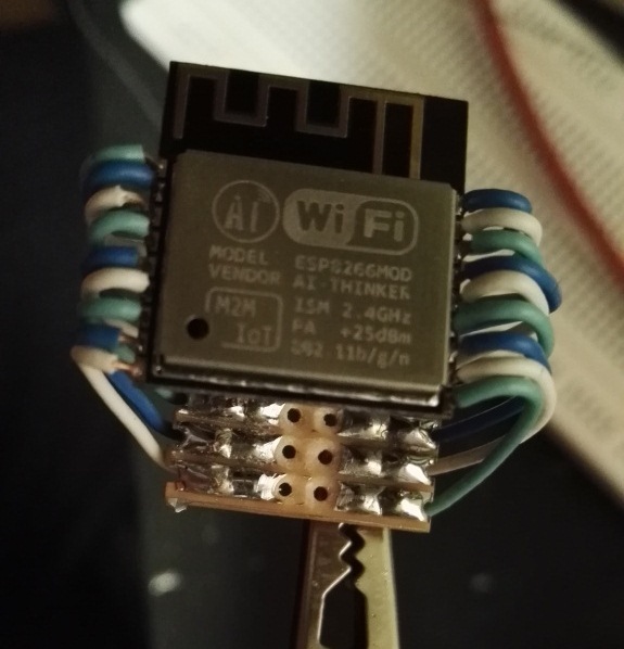
To be continued…
Monday, July 27, 2015
Interfacing TL5955 Using Arduino
You know those YouTube videos that make you think “Awsome… I want one?” well check this reactive LED table out:
Now,… to build an improved version:
Requirements:
- Multi Mode
- Clock Mode showing digital clock
- X&O Game
- Snake Game
- Sound Equalization’s
- Ping Pong Game
- More LEDs!!!
- Finer Resolution
- Fade Effect, Variable brightness Control
Yes the list may be ambitious, but lets see how it goes.
First up, Based on my donor table I can accommodate 48×27 (1296!!!) White LEDs Driving this array will require some thinking. I stumbled across the DADDY of all LED drivers made by TI the TLC5955. This bad boy can drive 48 LEDs using a single chip.
Hmmm… I have 27 Rows of 48 LEDs, I wonder if this one chip can be multiplexed to drive all 1296 LEDs! Let the games begin.
A breakout board was created as these (TLC5955) buggers only come in teeny tiny surface mount packages.
The TLC5955 is interfaced over serial communications, It has a single input register of 769 bits that must be written and latched.
If the MSB is 0 then the remaining bits are used to code the brightness of each LED using 2 Bytes (16bits) per LED. This means 0×0000 is off and 0xFFFF is full on.
If the MSB is 1 then when latched data is transferred to the “control” register, this needs to be done only once in most cases as this register sets global brightness and features.
Implementing the Arduino Code ( Why Arduino you ask?… because I got out voted by my team(I like PIC)):
There exists a library for the TLC5940 that I tried to use initially but soon after abandoned that Idea for code from scratch, come on how hard can it be to write serial data?
Turns out there are multiple ways of achieving serial communications
- Using the standard Serial.begin(); <-- maximum 115.2kHz
- Using software based bit bang, toggling a digital pin <-- CPU intensive
- Using SPI library on MOSI,MISO,SCK,SS pins <-- Can reach speeds of Fosc/2 (10Mhz for the ATmega2560)
It was easy enough to setup a new Arduino project that imported the SPI library. This can then be used to transfer data byte by byte. This was the problem… byte by byte? The guys over at TI have made my life hard by firstly not having a register that is a multiple of 8bits, forget that, each setting in the control data is either 3,5 or 7 bit combinations???
We therefore need a way to build up the bytes to be transferred. The register of 769 in code was increased to 776bits (97bytes) with the first byte 0000 000X where X is the control bit of the 769 bit register.
Using this method, the Control data was first written once on bootup followed by LED control data.
Now for the challenge… Can we multiplex this one IC to drive all 1296 LEDs? I got hold of a few 74HC595 serial in parallel out shift registers and have interfaced them to the arduino. each output of this shift register will enable a 48LED line therefore I need 4 of these ICs (8*4=32 >> 27).
That’s as far as I have got for now.
Monday, June 29, 2015
SIM Cards, Silent but deadly
Ever give much thought to the little piece of plastic in your mobile phone? No? That’s mostly because SIM cards are greatly misunderstood and perform their function extremely well. So what is it that I am getting at?
The SIM card is primarily your network identifier, it allows your device to identify and authorize itself on the home network. To do this it makes use of special security keys and algorithms. What you may not have known is that the SIM is the master of the phone, it has to possibility to dictate what the device should do.
The SIM can instruct the device to send an SMS, initiate a call, launch a web-browser, send a USSD, get network statistics including positional/location values and so much more. All this without user intervention or even consent!
Interested? In my proceeding posts I will dig further into how the mechanism around this work and how secure they may be.
Sunday, June 28, 2015
Data-Whaaat? A Simple overview of Databases
I work in an environment where databases (DB) are a way of life yet many people fear the DB. This should not be the case, if you are using Oracle or mySQL the basics remain the same.
A database is a collection of objects not tables!
People immediately think about database as tables of data, this is not the full story. A database is a collection of objects, common object are tables, procedures, constraints, index’s and jobs.
Objects are arranged/grouped in “schemas”!
^–get this and you are a database guru!
A database has one or many schema’s, a schema is normally associated with a user i.e you would log onto DBx.SchemaY where DBx is your main DB name and SchemaY is the name of a user. Within this SchemaY (or user) you have its associated objects(tables, procs ect. as mentioned above)
Each Schema is private!
The owner in possession of the schema password can “grant” other uses(i.e. their schema) access to his objects.
Queries
In 99% of cases anything before the where clause will not affect query speed! it is what comes after the “where” clause that affects speed.
Raspberry PI + 3G Dongle
Oh the headache! I believe after a week of fiddling I’ve final got my head wrapped around this madness.
There are two primary issues that need to be taken care of when using a 3G dongle with a PI
1. A USB modem has schizophrenia!
2. Network connectivity is not “always” available.
So what do I mean “schizophrenia”? Simple, the modem actually wants to a usb cdrom/flash and assumes this personality by default in most cases.
the command
lsusb
will list the current detected device. if it is not correct usb_mode_switch must be used to remind it that it should actually be a modem.
On point 2, sakis3g is a nifty tool to get you connected once you have figured out all of the “required” parameters. Its shortfall is that it never maintains the connection, i.e. if a connection is made and due to bad signal the connection is “lost” sakis3g runs like normal without ever telling you or attempting a reconnect. This is where UMTSkeeper comes in. This small yet feature packed tool maintains connectivity as well as logs network statistics! amongst other features that I have not played with.
Once you have all these 3 components working in harmony you should have a sweet “always” connected PI.